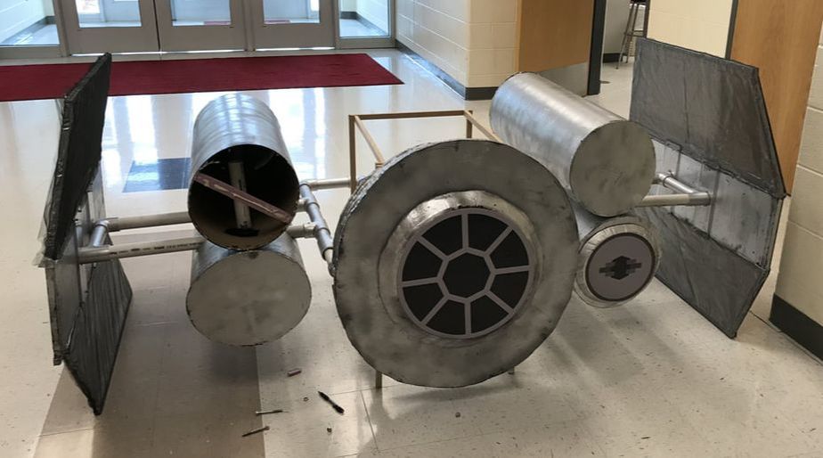
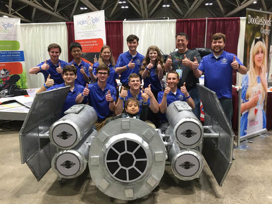
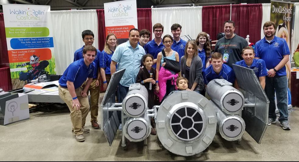
(Side note from Walkin’ & Rollin’ Costumes: What follows is a detailed documentation of the class project that was completed by Olathe Northwest Engineer a Better World Capstone. This was written by the students with photographs by the students and teachers. This Tie Interdictor wheelchair costume was completed with guidance by Walkin’ & Rollin’ Costumes to be presented at Planet Comicon 2017. An amazing job well done by an equally amazing group of young adults. Thank you so much for your dedication to the project. - Lon Davis, Owner, Walkin’ & Rollin’ Costumes)
Engineer a Better World
Walkin' & Rollin' Costumes Project
Olathe Northwest High School
Olathe Northwest High School
|
About
The 2016 - 2017 Olathe Northwest Engineer a Better World Capstone, as part of the Engineering Academy 21st Century Program in Olathe, is a team comprised of nine members. The capstone dynamically divides itself among different projects throughout the year, such as the Source America design project, the water baths project for the biology classes, the drip irrigation project for the horticulture classes, and, more notably, designing and building a costume for a child in a wheelchair in association with Lon Davis from Walkin’ & Rollin’ Costumes. |
|
How We Met Mr. Davis
Our group met Mr. Davis through Mark Gash and the City of Olathe People with Disabilities Advisory Board. Shortly after our communication with Mark Gash and Lon Davis, Mr. Davis visited our team and presented his previous work and what his work means to him, as well as what his future goals are. We quickly established a project with Mr. Davis, deciding on a costume to make shortly after his visit. Throughout the design and construction of the costume, Mr. Davis would come in to visit and ensure the project was running smoothly, helping with various tasks all while continuing production of his own. |
|
Brainstorming/ Design Plan
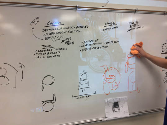
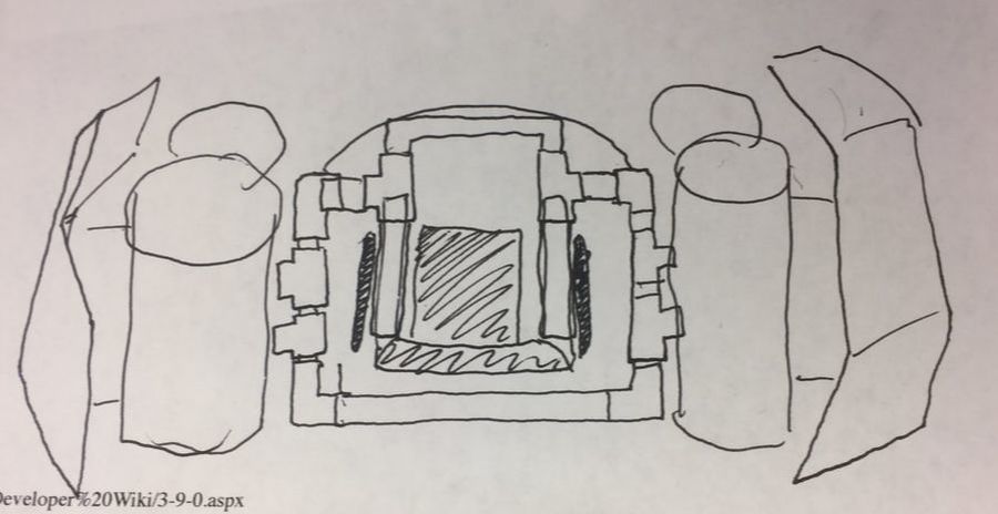
After gaining a basis of the parameters for the project, we had multiple sessions of which we focused on brainstorming together about possible designs for the costume. These sessions were extremely productive in making sure that everyone was on the same page for the design of the costume, as well as getting a chance for everyone to make their ideas and possible solutions known to the others on the project. Before every meeting and before we set to work on the project as a group, we all had a chance to sit down and brainstorm in order to make sure that everyone had a productive task to begin once we set out to work. This allowed everyone to collaboratively work towards the same goal, as well as make sure that any concerns about the project are addressed before everyone began work on their own tasks. This initial approach limited design fixation because each individual created personal outlines and ideas before coming together to decide on one solution. |
|
Cockpit
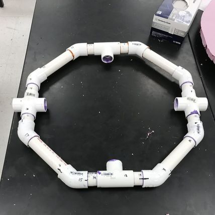
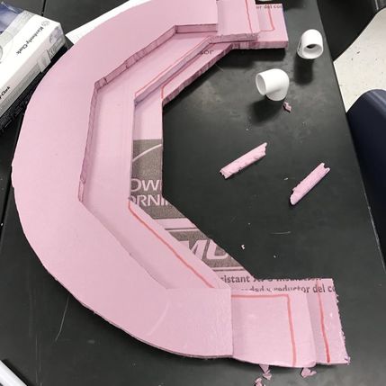
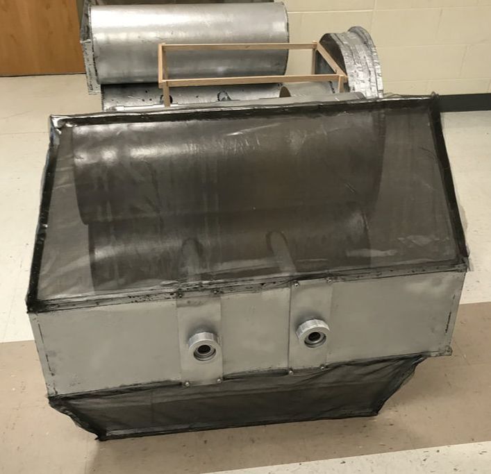
Materials: 16” Cylindrical Concrete Form Tube, Insulation Foam, Flex Seal, Spray Paint (grey), 1” PVC Pipe, 8-45 Degree 1” PVC Turns, PVC Primer/Glue, Vinyl, Phone (with music), Phone Holder, Wood Glue, and Liquid Nails Description: The cockpit was a crucial part of the costume. We constructed this piece first to relatively plan the size of the other parts and how we would attach them to the frame. We began our construction on a PVC ring that ran on the outside of the 16” concrete form tube in order to provide stability and attachment points for the frame. Simultaneously, we used a hot wire to cut the insulation foam in order to create a ring around the concrete form tube and mask the PVC ring. Once these pieces were complete, we glued and assembled them around the concrete form tube to create the initial frame of the cockpit. From there, we added attachments to the PVC ring that ran horizontally to serve as connections from the cockpit to the frame. We continued by covering the cockpit in Flex Seal and spray paint. Then, we bevelled and connected the front window to the cockpit using dowel rods and wood glue. Once everything was assembled and connected, we added the finishing touches: a vinyl window, vinyl buttons, foam attachments, and the phone accessories. Challenges: We experienced challenges throughout the construction of the cockpit that spawned from rookie mistakes. For example, while assembling the cockpit, we realized that we needed more foam to cover the entire width of the PVC ring. Also, we had to troubleshoot issues with connections between items that were already Flex Sealed, since many of our adhesives did not bond well to the Flex Seal. Although we had to overcome many difficulties in creating the cockpit, the challenges that we faced did not deteriorate from the quality of our product. Attachment Points: Extending backwards horizontally from the cockpit are two 1” PVC pipes that slide directly into the 1-¼” pipe that is used on the frame. This allows for easy detachment of the cockpit from the rest of the frame. |
|
Frame
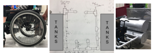
Materials: 1-¼” PVC Pipe, L Joints, T Joints, Adapters, Glue, and Primer; Nuts/Bolts (for connections); Zipties; Caster Wheels; Screws; Wood Blocks; Spray Paint Description: The frame was designed and built with flexibility and mobility in mind. Maintaining the client’s ability to move, as well as providing a platform that wouldn’t interfere with future expansion was a crucial part of the design process. Through many iterations, the frame focused on four key attachment points. First and foremost, the two extensions that held the handlebars were used as the primary mounting points. This allowed us to distribute weight easily, as well as give us the ability to make a square of sorts around the outside of the wheelchair, giving the user the flexibility to still access his wheels, and the designer the ability to build without fear of interfering with the design. The second set of attachment points were to the front wheel bars, allowing for secondary weight distribution. The first iteration was less than successful, ultimately being discarded for a few measurement mistakes, as well as the a non-functioning securement to the frame. The second iteration mad a few, mostly minor changes. It featured the same four point securement method from before, extending a few inches farther back. It featured a “Hook” system, where L joints and horizontal support latched onto the handlebars. Holes were drilled on both joint to be secured with zip-ties. The frame featured T-Joints on the front, with openings facing outwards. This allowed for the 1” PVC of the front of the costume to be easily attached and detached, granting the ability to get in and out of the costume easily. Finally, the costume had two T-Joints on either side of the frame, allowing for the wings to be easily mounted and dismounted. Pins were set to ensure that the costume remained stable. Challenges: Measurements were the most crucial aspect of creating the frame. Since we could not have the physical wheelchair with us to work with each day, we had to adjust measurements during each visit. We also created a wooden wheelchair frame to act as our guide for measurements. With that being said, it was difficult to create a frame that fit every dimension exactly how it was meant to. Attachment Points: The frame is the attachment base; it too has three separate pieces that sprout from it. On the front, it has PVC attachments areas to slide the cockpit into place. On either side, it connects and is bolted directly to the barrels and wings. |
|
Barrels
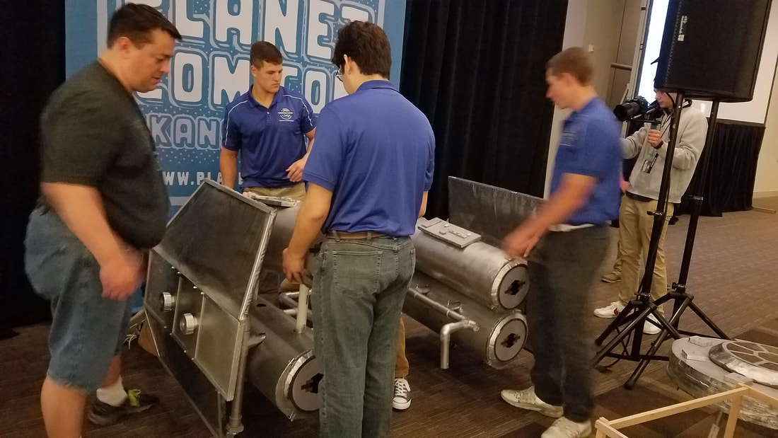
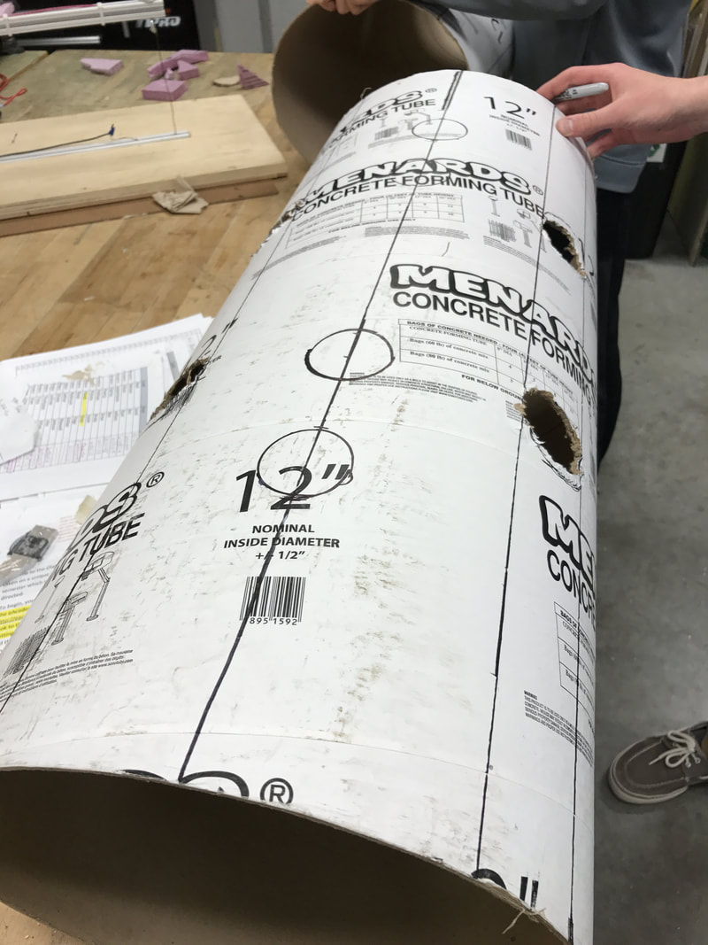
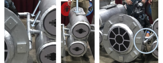
Materials: 12” Concrete Form Tubes, Insulation Foam, Flex Seal, Spray Paint, Zip Ties, Bent Metal Connectors, Vinyl Stickers Description: The barrels were a simple part of the overall product design, but they were crucial to constructing a costume that physically embodied the chosen design. To begin with, after purchasing the barrels and cutting them to their respective lengths, we measured each tube to determine where the PVC would connect. For the bottom barrels, we cut holes that ran through the barrels that would hold PVC to support its weight. The top barrels only had two holes that vertical PVC would run through to hold them stationary. Once the holes were cut, we cut and glued the PVC to run horizontally through the bottom barrels, connecting to a tee joint that runs vertically into the top barrels. Then, we covered everything in Flex Seal and spray paint. After finishing the construction of the main aspects of the barrels, we individually measured the ends of each barrel to create covers for the bases. This challenged us because we experienced difficulties using adhesives between the covers and the barrels. We ended up using bent metal pieces and Zipties to attach them together. We then added vinyl stickers and bevelled portions to the fronts of each barrel. In the end, nuts and bolts were used to attach detailed pieces to the top of the sets of barrels. Challenges: The most troubling situation experienced while constructing the barrels dealt with attaching the covers to the ends of each barrel. We tried adding crossed beams and using countless adhesives (liquid nails, hot glue, wood glue), but none of these provided adequate support for the covers. By switching to metal pieces and Zip Ties, we eliminated the adhesive issue. The only other difficulties with this portion dealt with the structure of the barrels and how they would attach to the frame. By running the PVC frame through the barrels, we ended up creating stable and detachable pieces. Attachment Points: The two bottom cylinders attach to the main frame through the PVC pipe that runs through them. They connect to the main frame using bolts that run through drilled holes in the PVC. On the other side, the barrels are attached to the caster wheels and frame directly through the PVC output. The two top cylinders slide on top of the bottom cylinders though PVC which vertically cuts through the bottom cylinders. |
|
Wings
Materials: Pine trims, Tulle, Thin Silver Fabric, Foam, Flex Seal, Spray Paint, Staples, Bent Metal Connectors, Screws, Nails, Lexan, PVC/Connections, Nuts/Bolts, Stainless Steel Adjustable Clamps Description: The wings were a crucial part of the costume. We began dimensioning and design once the tanks and the cockpit were completed. The main goal was to make the lightest wing possible so that the costume could be stable. We started this task by drawing out what the wing would look like. We then referenced many images of the TIE Interdictor to make the wing more movielike. This is why we constructed the wings to be angled. The wood was cut with a miter to have the wing lean 15 degrees forward and taper in. Once the wood was cut, we glued and nailed the pieces together. Since, the joints were not very secure we ended up making metal bracket to fit on the joints that were screwed into both pieces of wood. We then cut out the foam for the inside of the wooden rectangle. After all of this was completed, we applied Flex Seal to the entire wing to make it weatherproof. Because the PVC had to intersect through the foam, we decided to reinforce the foam with Lexan sheets with two large holes as an insertion hole for the PVC. This piece was screwed into wood frame. Then, we stapled the tulle onto the frame. This was then covered by wood trim. Two caster wheels were attached to the middle of the connection PVC to the frame for increased stability and mobility. Everything was then spray-painted to arrive at the final product. Challenges: We definitely had a few challenges along the way. The first main challenge was the cutting of the miters for the wings because the cuts needed to be mirrored. In addition, we had issues with the cuts being exact which then hindered the stability of the joint. We then had issues with the wood splitting when the staple gun was used. Once the spray paint was applied, we had issues with the foam deteriorating in response. The fragility of the wings was also an issue when attaching them to the frame. Attachment Points: The wings attach to the frame with two bolts. PVC runs through the wings and is capped on one side and slides into larger PVC on the frame. We drilled holes through the inner PVC and the outer layer of PVC to allow for a bolt to secure them together. |
Assembly Guide
- The handlebars are taken off of the wheelchair.
- The frame alone is attached to the wheelchair by zip ties. This helps secure all of the joints.
- The wings are then attached to the parallel sets of PVC on the frame. The wings need to be pushed in until the holes line up to allow a bolt to secure the wing’s PVC into the frame PVC.
- One bolt is placed in each hole and secured with a nut.
- Step three and four are repeated on the other side for the other wing.
- The two extra tanks are placed directly on top of the other two tanks that are attached to the wings. There are holes on the bottom of the two extra tanks that allow for them to be slid onto the PVC that is vertical and parallel. There should be two tanks on each side that are stacked on top of each other.
- The front/cockpit slides into the frame on the left and right with the corresponding PVC connections.
|
Presentation
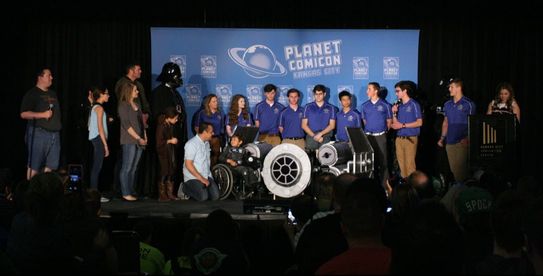
When we were approached by Mr. Davis with the idea for a project, we were offered the opportunity to present this project as a gift and somewhat of a surprise to a client during the opening ceremony of Planet Comicon. This reveal took place in front of around 100 people in person, and broadcast to around 10,000 throughout the convention, as well as on television. Our project manager and lead designer were given a moment to speak about our program, capstone, and project, as well as the design process and meeting with Davey and Mr. Davis. Immediately following the opening ceremonies, we took the pieces to the actual convention floor and assembled them at the Walkin’ N’ Rollin’ booth. We ran into slight difficulties with attaching the zip ties, but were quickly able to fix them. We noticed that one of Davey’s wheels was also having trouble gaining traction, potentially due to the PVC-Caster Wheel attachments being attached too high. Davey’s father was able to successfully push him around, and after a group picture, our presentation was complete. |
The Engineer A Better World 2016-2017 Group presenting during the opening ceremonies. We were accompanied by Walkin’ N’ Rollin’ founder Mr. Lon Davis, The Uria Family, Actor Spencer Wilding, and our client, Davey Uria.
|
Future Recommendations
|
Meeting with Client:
|
Brainstorming:
|
Build Phase:
|
Management:
|
|
Closing Remarks
The 2016-2017 Engineer A Better World team would like to thank Mark Gash for putting us in contact with Lon Davis, and with providing us with many opportunities during the year. We would also like to thank Mr. Lon Davis and the Walkin’ & Rollin’ Costumes team for all the assistance during the actual design and construction process. This experience was incredible for our team. To see the joy and excitement that our product brought to Davey’s face made the project worth it for everyone. Although we experienced challenges and difficulties throughout the design process, this project was a successful way to incorporate the fundamental principles of engineering to create a functioning and useful product. |

